Layout Diary & Description of Events
Archive: 2015
This page is set up so that the newest information is at the top.
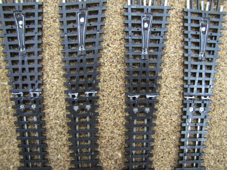
December 26, 2105 - January 3, 2015 – Happy New Year! More Of The Same, But Great Progress! (17 January 2016)
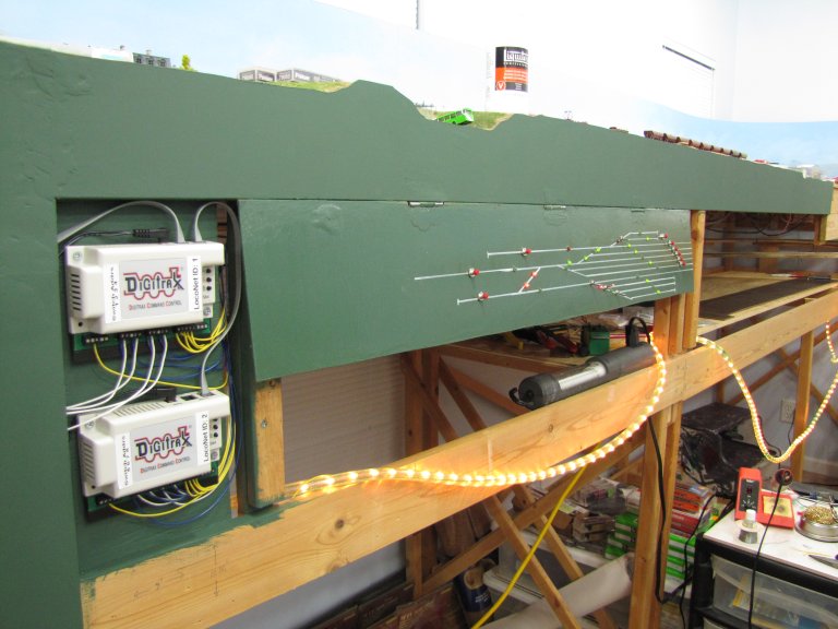
The title says it all - more of the same. I made incredible progress on installing and wiring up signals. I figured out a way to have the four Ausfahrt Signals show the proper aspect by using the internal switches on some of the Tortoise switch machines. All four signals are displaying the same aspect for the single-tracked following block. It's boring, plus it indicates that trains on all four track could proceed! I wanted something that was a little more intelligent. I set up the signals so that, if the proper switches were aligned, the signal would indicate the occupancy state of the following block. The other three signals would indicate "double-red", since the switches weren't set to those tracks. After a BUNCH of trials and tribulations, I was able to get it to work... mostly. I have handwritten diagram that I plan on converting to a jpg file. I'll post it here when I get to it. I can tell you that the diagram has saved me from making a LOT of errors. I refer to it every time I'm working on the signals.
OK, so what did I get done? I installed 2 Block Signals on the lower level and 2 Ausfahrt Signals (for Track #4 and Track #5) up in Murnau.I also "planted" the Einfahrt Signal on the north end of Murnau - but I didn't get a chance to wire it up. I wired up the Block Signals to the appropriate SD-1s. The Ausfahrt Signals were a bit more complicated because of the involvement of the Tortoise switches. I will tell you that I used a LOT more isolating diodes than I had ever planned! Power was just leaking to the signals from everywhere! My upcoming diagram will explain this issue and the location of the diodes.
I also installed opto-sensors between the ties for two blocks - the one coming out of Staging, and the one for the helix. Each block requires 4 opto-sensor - two at each end of the block. Once installed, I wired all 8 sensors to the appropriate BD-1 boards.
December 19-25, 2015 – Merry Christmas! Boards, Signal, Mounting and Wiring - And, Time For Another Diagram! (25 December 2015)
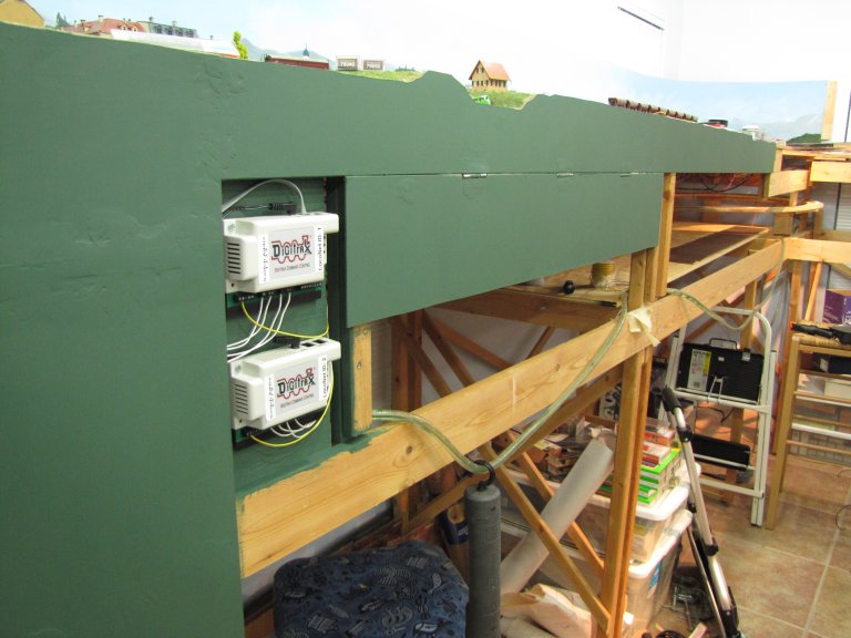
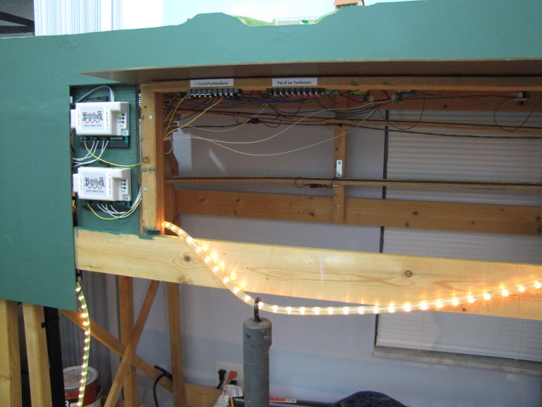
During the holiday break so far, I've been able to accomplish quite a bit - even if it doesn't really show. I started out the weekend prior to my holiday break (December 12-13) by building a board that would contain most of the BD-1s and SD-1s for the north half of Murnau and down into Staging. I added these nice PCB mounting tracks (PCMT) to the piece of plywood so that I could easily add the Circuitron boards later. Oddly enough, these PCMTs were manufactured by my old company - Tyco.
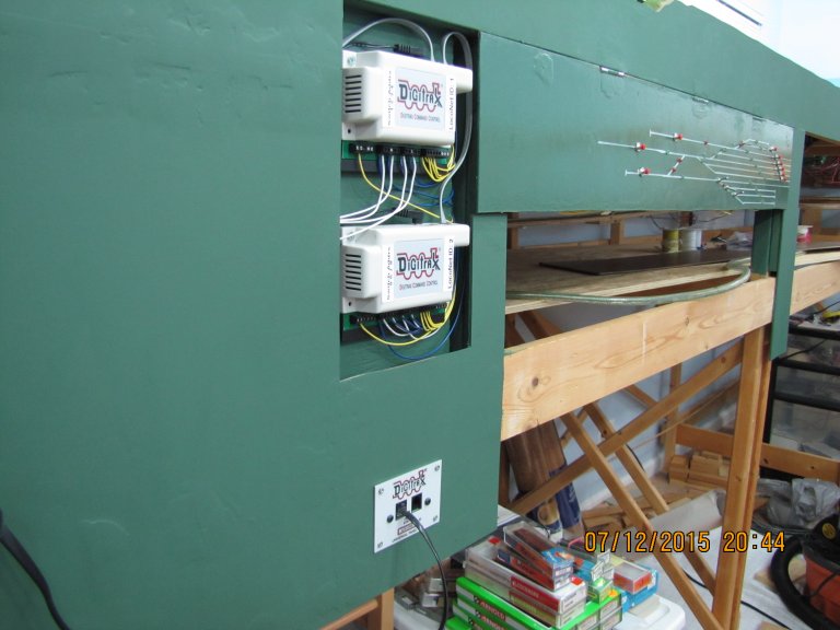
This past week, I've been adding the BD-1s (3 of them) and SD-1s (7 of them) to the PCMTs and wiring them up. It was beginning to get confusing, in terms of what board/block relied on another. So, I created yet another diagram. This one has the wirings between BD-1s and SD-1s - without all of the signal, detection and power wiring. I normally throw my pics and diagrams in at the end of my entry, but I'm going to make an exception today. Here's the diagram:
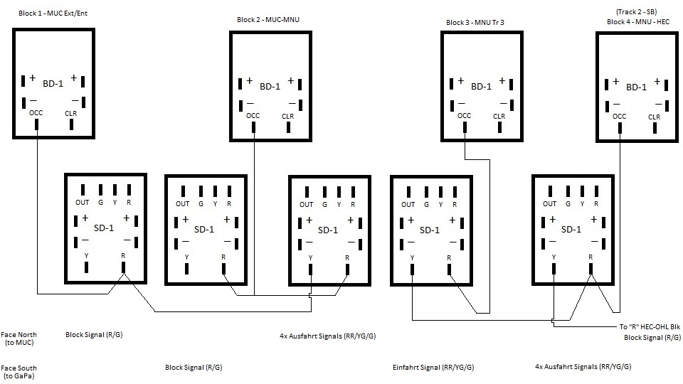 |
| This
shows the block detection boards (BD-1), and how they're wired to
the signal driver boards (SD-1). This diagram is for the first block
out of Staging, the block that contains the helix, and the block
that contains Track 3 in the Murnau Bahnhof. The fourth BD-1 is for
Track 2 in the Murnau Bahnhof. However, this is not a section of the
line that I will be working on over the holiday break - unless my
sources for the boards and signals come through for me quickly. Note that only the SD-1s that are driving Einfahrt (entrance) and Ausfahrt (exit) signals require hooking up to the next block's "Y" post. This is needed in order to show all three aspects - DOUBLE RED = block is occupied, GREEN/YELLOW = block is clear, but the following block is occupied, GREEN = all clear. The first two SD-1s only drive block signals, which are either RED (block is occupied) or GREEN (all clear). |
I'll try to get a couple of photos in here before my break ends. I have the board wired to the point where I should be able to install it. There is some wiring that you simply can't do until it's installed at it's final location.
I have installed three of the actual signals on the layout - 2 Block Signals and an Einfahrt Signal. I have 4 Ausfahrt Signals that still need to be installed. I'll try to snap some pictures of those as well.
I also have the holes drilled between the ties for the opto-sensors. I have the sensors installed, but I need to pull them up in order to add some feeder wires to them - the legs aren't really long enough to do anything with them once they're installed, making soldering to them difficult or next to impossible.
My goals is to get this whole section installed and tested before I have to go back to work. If other boards and signals show up in the meantime, I might try to work on those as well. Before I do, however, I'll be creating yet another diagram - so that I have it down on paper before attempting any work.
Stay tuned...
December 6, 2015 – This Is Getting Tricky - Time For A Diagram! (6 December 2015)
My experiments continued this weekend, but at a slower pace than I had hoped. On Saturday, I was two hours into a diagram when my laptop, for some unknown reason, decided to shutdown. The diagram was in Paint - the free one that comes with Windows - and it has no backup mechanism. I had just considered saving the file when it shutdown. I was furious! I stopped for the day at that point, and watched an Iowa basketball game until the beginning of the Big Ten Championship game where Iowa played Michigan State. That didn't turn out any better, but at least it was a very good game!
So, I recreated the diagram on Sunday. I did some experimentation with the Exit Signals after an e-mail exchange with Steve at Circuitron. For instance, in order to head north out of Murnau, there will be four separate Exit Signals. The way I was going to originally wire them up was using a single SD-1. That would mean that each signal would have the same aspect. When the following blocks were clear, all four signals would be green. I got to think about what I had seen, personally, in Murnau, and that didn't make any sense. It seemed like the only signal that was green (or green/yellow) was the track for the train that was about to depart. Hmmm... OK, so how could I replicate this on my layout? Then it hit me - I have the Tortoise switch machines, which have two electrical switches built in! I was using one set for frog polarity. However, the second set was unused! I had it in my head that if the switch wasn't properly aligned for the mainline, the associated signal would always be a double red. This wouldn't be perfect, as there are a couple of tracks where several switches that need to be thrown in order to be properly aligned for the mainline. But, it would certainly be better than showing that ALL track were clear to go!
I've attached the diagram below to show my solution. The Tortoise ends up being the key in this setup, as it determines whether signals are lighted via the SD-1 board and its (and the BD-1's) logic, or if we simply see a double red. This is accomplished by utilizing one of the switches on the Tortoise. In the diagram below, I'm using pins 5,6, and 7, which is the second switch. If the turnout on the layout is properly aligned for the mainline, then the SD-1 is powered. The negative wire from the power supply is routed appropriately by the Tortoise. If the turnout is NOT properly aligned for the mainline, the red LEDs in the signal head are lit directly, with no possibility of lighting the green or yellow LEDs.
Note that I had to add an isolating diode (1N4001) between the red LEDs and the "R" terminal on the SD-1. This is to prevent power from routing through the red LED and lighting up all of the other LEDs.
For the white LEDs, which indicate that shunting can still occur, regardless of a red aspect, I have wired them to a toggle switch for manual operation. The diagram shows that they get power, regardless of the Tortoise/turnout position. I think that's the way I'll go, but I'm still up in the air about it. I may only allow those to be lit when the turnout is properly aligned.
This doesn't seem like I got much done this weekend. However, there was a LOT of experimenting involved. Also, I spent almost 5 hours on the diagram - 2 hours of that work was wiped out on my first attempt - see my first paragraph in this entry. Grrrrr!!!!!
Next weekend, I'll probably continue to experiment. We have company coming this weekend, so I probably won't be drilling holes in the layout for installation. But! Never say never!!
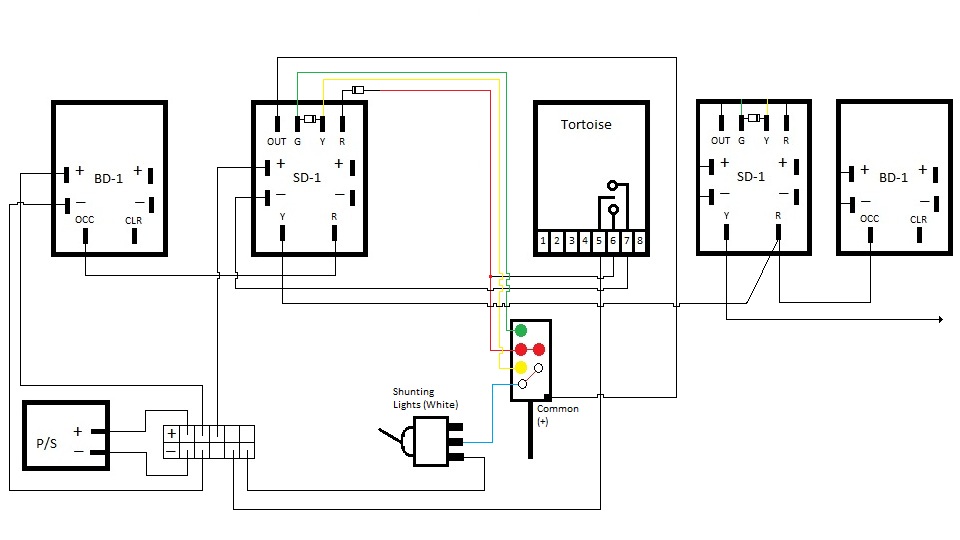 |
| This is how I plan on wiring up the signals for at least Murnau Bahnhof. The Exit Signals have a set of two white lights that are used to allow shunting even when the signal aspect is red. Entry Signals and Block Signals will be much easier to wire. |
November 29, 2015 – It's Beginning To Look A Lot Like Christmas - With Green And Red (And Yellow) Signals, That Is! (29 November 2015)
OK, so a Thanksgiving holiday that was trashed because of a Thanksgiving night UCF football game, actually turned out well. We headed to the Tampa Bay area on Wednesday (because we had a non-refundable night at a hotel, and we wanted to see friends from my Paradyne days), and then to UCF on Thanksgiving to the final defeat of an 0-12 UCF football team at the hands of USF. There was talk of heading back to Tampa for a Friday get-together with Tina's family. Kerstin was still sick from her long days the previous weekend at the FMBC State Finals (where her Park Vista Performers marching band were crowned Class 5A champs for the second year in a row!), and Tina and I were both over long car rides. So, it was agreed that we'd just head home on Friday.
This gave me two days to putter around the layout. Saturday was spent cleaning. I cleared everything off the second piece of Staging and moved it to it's proper location. With the exception of a few short pieces of missing track, the lower level looked pretty cool! I vacuumed, cleared my main work area, and organized a few things, in preparation for testing some signals and block detection. I suddenly realized that everything I had planned for the tests had been erased from my mind. So, I had some reviewing to do. I headed to the Circuitron and Viessmann websites to check out various wiring instructions. That pretty much filled up my day.
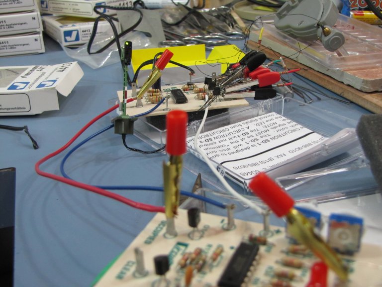
Sunday was when the real tests began. With instructions and a laptop at my fingertips, I opened the first BD-1 block detection board and SD-1 signal driver board. I also opened up a Viessmann exit signal. I added an isolating diode between the green ("GD") and yellow ("YD") lugs on the SD-1, as suggested by Steve at Circuitron. This would allow for a green/yellow (caution, next block is occupied) aspect, instead of just yellow. Then, I simply hooked up the BD-1 and SD-1 together as suggested by Circuitron. I then added the Viessmann signal to the SD-1. Finally, I added the opto-sensors BD-1, hooked up power to both boards, and then did the sensitivity adjustment on the BD-1 for these sensors. Hmmmm.... that's strange. The second detection section isn't showing up. I checked and re-checked my wiring to ensure I had it right. Everything looked right, but all I was getting was a double red signal. I did move the wire that connects the SD-1 to the BD-1 to see the signal transition from green to green/yellow to double red, which was cool. However, that was a manual test to check the signals. That didn't solve my problem.
OK, time to try another BD-1. I disconnected the original BD-1 and connected a different BD-1 just as I had done previously with the first one. Hey! That worked! I was getting green and double red!! This was expected, as you'd have to have two blocks hooked up to see the green/yellow aspect. Cool! But, what was the story with the original BD-1? I flipped the board over and noticed that a trace to one of the pins for the sensitivity dial was not completed. I have e-mailed Steve at Circuitron to see what he would like me to do. I suggested that I could attempt to complete the trace, but didn't want to void the warranty. Or, I could simply return if for a replacement - or try both. Stay tuned to find out how this pans out.
All in all, I was extremely pleased with how the experiment turned out. I may try to wire up two blocks - to make sure I know what I'm doing - prior to heading to the layout. There is a set of white LEDs on the signal head, which are used to indicate that it's OK to shunt while there is a red signal. These will be turned on by a manual switch, so I should probably test that as well. Also, if this works - and there's every indication that it will - I'll need to make another large purchase from both dealers where I get my Circuitron and Viessmann items. Christmas may come early, if I can get another weekend or two in on this prior to my vacation!
Here are some photos from this weekend:
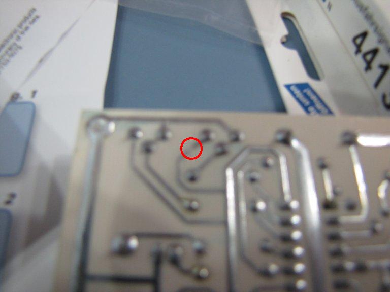 |
| Here, you can (barely) see the break in the trace on the BD-1. This is what caused me to be unable to adjust one set of opto-sensors. |
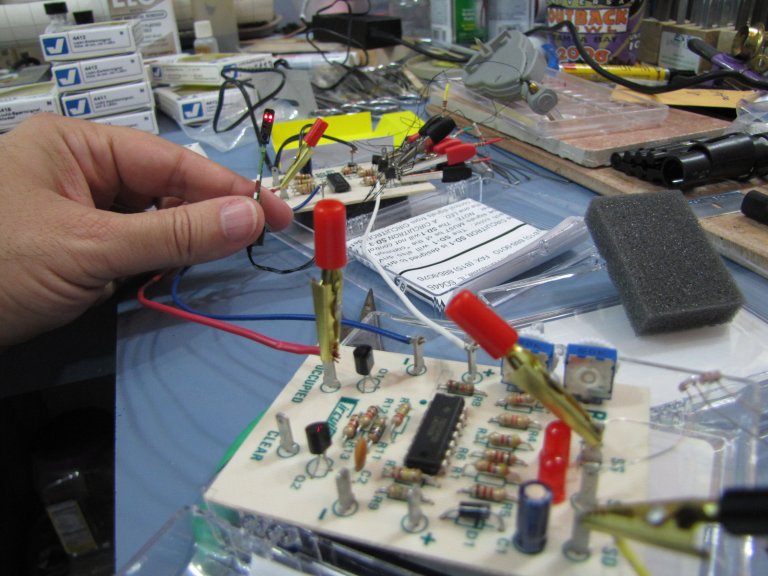 |
| Here's the test rig. In the foreground is the Circuitron BD-1 block detection board. In the right foreground, you can just see a pair of the opto-sensors. The board in the background (with all of the alligator clips) is the Circuitron SD-1 signal driver board. I'm holding the Viessman 4413 N Scale "Licht-Ausfahrsignal" (Lighted Exit Signal). |
 |
| Same setup, but the signal is now green after sliding my finger over a pair of the opto-sensors in the proper direction. Cool! |
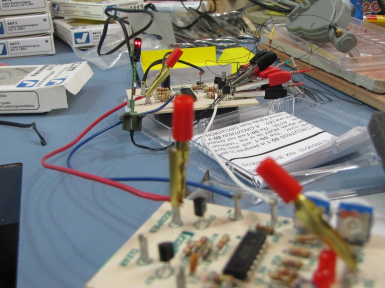 |
| ...and back to double red after swiping my fingers in the opposite direction over the opto-sensors. As you swipe (or as a locomotive/car would travel over) the opto-sensors, you see the red LEDs in the very foreground light up. These LEDs are also used to set up sensitivity. The blue squares you see on this board have a white dial on the other side, which is used for the sensitivity adjustment. |
November 17, 2015 – The Stars Align For One Weekend (17 November 2015)
No marching band competition, Ft. Lauderdale Strikers and Park Vista HS Football seasons are over, no UCF football game, and no Bundesliga matches because of an international break. Oh! And, Iowa's football game against Minnesota is a night game. That can mean only one thing - it's time to head out to the layout!
I was a bit sluggish getting out to the hobby room on Saturday. It had been 6 weeks since my last foray, and I was trying to figure out what I needed to do. I didn't get out there until about 2:00PM. I had actually read my previous entry to try to refresh my memory, so I knew I still have to lay some turnouts on piece of plywood that was to be the far end of Staging. Once, I got out there, this is exactly what I worked on, so it was good to review my blog! I spent several hours on Saturday and Sunday on this.
I added all of the feeder wires to the turnouts, drilled holes for those wires, and installed the turnouts. It went very smoothly - even the plastic, insulated rail joiners! Then, as I was ready to install the last turnout on Sunday, it hit me - I hadn't drilled the 1/4" holes for the actuating wire on the Tortoise switch machines...AGAIN!!! I couldn't believe my eyes! You'd think I'd learn from my mistakes, but no! So, I carefully lifted each turnout up and nudged them to the side so that I could drill each hole. Finished! The only thing left to do is to add the track between the two sections of Staging. That won't get done until I am ready to permanently connect them. First, I'll turn my attention to the Viessmann signals and Circuitron block detection boards.
This Thursday is a UCF football game in Orlando, followed by the Florida Marching Band State Finals in St. Pete this Saturday, where my daughter's band will try to extend their unbeaten streak (14-0!) in Florida by capturing their second straight state championship. The following week is Thanksgiving. I'll be spending that at yet another UCF football game (Gee, THANKS, ESPN!), which will likely be my son's last performance as a UCF Marching Knight. Next year, he'll be very involved in his upper level courses for his Aerospace Engineering degree. Depending on when I get home from all of this, I may get a chance to head out to the hobby room. If that is the case, I'll probably clean everything up, so that I'm ready to work on the Viessmann signals. I'll also try to take a picture or two.
September 27, 2015 – Welcome To Marching Band Season! (27 September 2015)
As if having season tickets to Park Vista HS Football, UCF Football, and the Ft. Lauderdale Strikers weren't enough distractions, this weekend marked the beginning of "marching band competition" season. I also watch the Iowa Hawkeyes football games and the Bayern München soccer matches - or any other Bundesliga match, for that matter. So, Fall is full of a LOT of distractions. Saturday saw the Park Vista Striker Cobra Marching Band (now called the Park Vista Performers - but I don't like that name) take top honors at the Cavalcade of Bands competition at Boca Raton HS. The band hasn't lost a competition in Florida since November, 2012, which is absolutely unheard of. As far as I know, no other band has done this in Florida!
Football, soccer and the band competition pretty much killed Saturday. I wandered out to the layout for a couple of hours to modify some more turnouts for the final piece of Staging.
I got up at 7:30AM on Sunday so that I could head out to see many old and dear friends from the Florida East Coast Railway Society. This year's convention was in West Palm Beach, so I went up to the convention site to take in the traditional operating session of fecNtrak - the final activity of any of our annual conventions. It was great re-connecting with so may guys and gals that enjoy trains even more than I do!
OK, so, enough of the excuses for why I didn't get much done this weekend. The main reason was that I was simply lazy. I managed to head out to the layout for another couple of hours on Sunday and continue to work on modifying some turnouts. All I have left is to clear some plastic under the frogs and add a green wire. Once I'm ready to lay the turnouts, I'll also have to add feeder wires at the heel of each turnout as well.
Next weekend is another band competition. This one is a quite a bit further away, so working on Saturday will likely not happen. I have the Viessmann signals in-house now, so I need to start experimenting with those. I may clean up my work area on Sunday, in preparation for a test setup. I'm really excited about hooking up the Viessmann signals to the Circuitron BD-1s and SD-1s in order to try out the block detection and signaling that I have planned. If this all works, it'll be the final piece of the upper level - along with wiring up the Tortoises to the DS64s and the second control panel. Once that is all done, I can make the Staging level permanently installed and begin wiring up that level. I'm expecting to be working on most of this during the Christmas holidays, when I SHOULD have 2 weeks off.
September 20, 2015 – Popping The Cork! (27 September 2015)
With a Park Vista home football game on Friday night, and a UCF home football game Saturday night, I knew I wasn't going to get much done this weekend. Once I got home from Orlando on Sunday afternoon, I did manage to head out to the layout for a couple of hours. I cut and glued down the cork for the the plywood that will represent the remainder of the Staging level. After gluing, I put some tiles on top of it to hold it in place and then called it a weekend.
September 13, 2015 – Finally! A Full Weekend - Interrupted By Bayern And Iowa (13 September 2015)
The Bayern München vs. Augsburg match, plus the Iowa vs. Iowa State football game broke up my Saturday considerably. However, both of my teams won, so it was worth it! In spite of these distractions, I was able to put several hours in on both days this weekend - making up for the fiasco a few weeks ago.
I was able to complete the large section of track for the staging level on Saturday! I also added some bracing that I'll need for this section on the lower level. One of the braces needed to drop below the base of the level in order to accommodate a Tortoise switch machine. The other brace was level with the base, as there are nothing but 14 straight tracks at that location.
Once the bracing was in place, I placed this section of staging at its final location. For now, it can't be permanently installed because I still need to install signals to the Murnau Bf, which is directly above staging. Speaking of signals, I was informed this week that my Viessmann signals are finally in, and were shipped off to me on Friday! That's very close to perfect timing! This will give me a chance to finally finish up the top level with Murnau Bf! I already have the detection boards from Circuitron. However, they're pretty much useless without the signals. I'm guessing there will be a lot of experimentation with these signals and boards between now and Christmas. It would be great if I could get these all installed prior to that, but my weekends are booked solid between now and Thanksgiving. We'll see.
I finished up on Saturday night by removing the 3 sawhorses that were used when working on staging and cleaning the entire layout room. There were lots of pieces of cork, sawdust (from drilling holes), wire bits, and general filth due to weeks of work on this section of staging. It was nice to have a clean area to move around again - at least for one night.
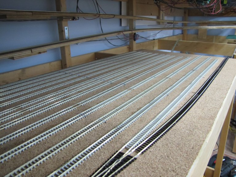
Sunday found me pulling 2 of the 3 sawhorses back into the layout room - but only after I had cut down a piece of plywood that would serve as the other (smaller) section of the staging level. This section will contain the ladder for the other side of staging, which includes the 3 thru-tracks and the 5 stub-ended storage tracks for Garmisch-Partenkirchen. After cutting the plywood to size, I brought it, and the 2 sawhorses, back into the layout room. I glued down cork on the plywood, added weight, and left it to dry.
Oh, some good news on the programming track with the dead section for protection. It turns out there are 4PDT switches! It never occurred to me, but my friend from work mentioned them when I was explaining my issue. I figured there was a simple solution - I simply didn't know about these switches. Problem solved!
Here are some pics of the staging section that I completed, placed under the layout.
 |
| The far end (or "Garmisch-Partenkirchen end") of staging. The new piece that I'm working on will complete this level. It will contain the ladder for the storage tracks on the far side, plus the 3 thru-tracks in the middle. The track with the wooden ties is the "Programming Track". I still need to make a couple of cuts in the rail to create a "dead section" while this track is in "Program Mode". |
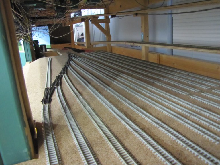 |
| A view of the ladder for the storage tracks representing München. Note the extra track attached to the reversed switch. This will be my "Extra Power Track", where additional locomotives will be stored. |
 |
| A view of staging from the far
end. From left to right: 1x Programming Track, 5x München Storage Tracks, 3x Thru Tracks, 5x Garmisch-Partenkirchen Storage Tracks. |
 |
| A view of staging from the near end (or "München end"). Note the 5x stub-ended tracks on the left, which represent Garmisch-Partenkirchen. The next three tracks are thru-tracks, allowing for continuous running, and also allowing a locomotive to perform a run around of its train so that it can head back in the opposite direction (assuming that it isn't push-pull). The next 5 tracks represent München. And, as mentioned, you have the Extra Power Track and the Programming Track. |
September 7, 2015 – Long Weekend, But Only "Labored" On Labor Day (13 September 2015)
Labor Day Weekend was broken up by lots of different activities that didn't really make it easy to "get all sweaty" for any appreciable length of time. So, I had to wait until Monday before I could spend some time on the layout. As has been the case for almost a month and a half, the hot topic was the staging level. I added another turnout at the front of staging so that I could install a programming track. So, for section of staging representing München and parts north of Murnau, I now have 5 stub-ended storage tracks, plus a stub-ended programming track. I also have a stub-ended track that I'm calling the "Extra Power Track". I plan on keeping additional locomotives on this track, so that I can swap them in and out on occasion.
I'm still thinking about how I want to handle my "drive-on" programming track. I was a dead section between the rest of the layout and the programming track when it's in "Program Mode". I want to do this with a single flip of a switch. I still need to figure this out. I'm going to ask a friend of mine at work next week who is an electrical engineer. I'm sure it'll be simple - I'm just not seeing it, is all.
August 30, 2015 – Sunday Is No Day Of Rest! (13 September 2015)
This weekend found me with a few hours on Sunday. So, I continued my work on the staging tracks. I added the 5 stub-ended storages tracks towards the back of staging, which represent Garmisch-Partenkirchen, and destinations south of Eschenlohe. This was fairly easy work - no turnouts. This was straight track which I simply need to solder feeder wires and drill holes for those wires. Considering I only had a few hours, I got quite a bit done!
August 22, 2015 – A Few Hours On Staging And Then Pack For Seattle (13 September 2015)
I was able to sneak into the layout room to do some work on the staging tracks. I lengthened the 3 thru-tracks and also worked a bit on the stub-ended storage tracks. There wasn't really much time to do anything else, as I needed to get ready for my business trip to Seattle on Sunday.
August 16, 2015 – Derailed By AT&T Wireless! (16 August 2015)
Well, my last full, free weekend for awhile was completely trashed by work. One of our customers, AT&T Wireless, is unnecessarily throwing their weight around, and my team had to suffer for it. Several people on my team (including me!) have put in around 120 total hours of work in 7 days. That's right - 3 weeks' worth of work in 7 days - an average of 17-18 hours of work each day. The only reason I was able to add these two entries is because we're waiting on the build and deployment process. I have next Saturday open, so far. I'm hoping to get the rest of this section of Staging completed at that time. Crossing my fingers that another emergency doesn't pop up in the meantime.
August 8,9, 2015 – More Staging - Less Turnouts (16 August 2015)
My son was home from college, so I was a bit distracted. However, I did manage to make it out to the layout a couple of times. The really good news was that I didn't have to completely pull up all of my turnouts in order to drill holes for the Tortoise switch machines. I had to disconnect a few, but they went right back together minimal effort. Weekend disaster averted!
So, I used the regained time to lay a couple of turnouts and then start on long, straight sections of track. The progress was certainly more obvious, as laying straight track is about as easy as it gets! I will have to modify the track that I laid that is closest to the front of the layout (far right in the photo below), however. I want one more turnout. I'm trying to figure out how to make that one a programming track if a switch is flipped. I'll need a dead section between it and the turnout while it is in programming mode. So, I need to figure how I want to wire this section, and if it can be done in a fool-proof manner at all.
 |
| A view of the Staging tracks with some of the straight sections added. The track in the opposite direction is a good candidate for a programming track. I intend to add one more turnout, just past the cut-out on the right. Once that track is laid, that could also be considered for a programming track. |
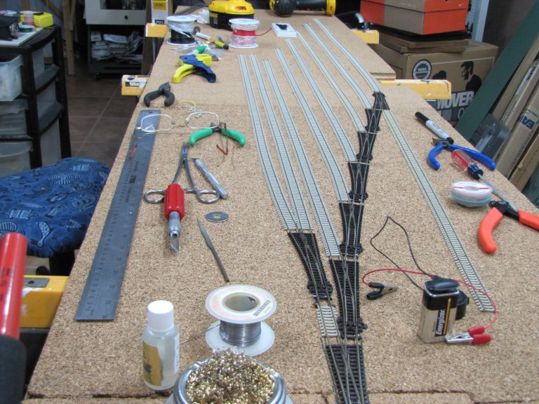
August 1,2,3, 2015 – Staging - The Agony Of Laying Turnouts (3 August 2015)
We had visitors this weekend, so it was difficult to focus on the layout. On Saturday, I snuck into the layout room for an hour or two. I tried adding clear nail polish to about a half dozen or so turnouts to see if this would fix the electrical short issue that occurs when the the back of the wheels from 2-axle freight cars graze the closure rail. Well, it failed miserably. However, while testing this out, I noted that only one car was causing the issue! So, I took the wheels off this car and adjusted them slightly. I couldn't find my N scale wheel gauge, so I winged it. I put the wheels back on the car and manually ran it though the turnouts - trying my best to get the wheels to come in contact with the closure rail. I couldn't cause a short - cool! After that, I ran this car on the back of a train, going forward and backward through lots of turnouts, including a backing move that involved five turnouts in a row - nothing! So, problem solved - at least until I find another car whose wheels are out of gauge. That was it for Saturday.
On Sunday, once our visitors had gone home, I started laying track on the piece of plywood that would be part of Staging. I was really excited at the prospect of laying new track. That excitement immediately vanished as I started working on the yard ladder. Ugh... I began to remember what a pain it was to lay turnouts. Lots of hole-drilling, soldering between 2 ties, and the bane of my entire existence - plastic, insulating rail joiners!!! I absolutely loathe these things! I considered using metal rail joiners and then cutting each rail at slightly staggered locations. This wouldn't really work on the ladder as things are too compact. I came to the realization on Monday night that the yellowish plastic joiners were old and may have shrunk. I tried some that were more white on Monday, and these worked very well. That didn't help me on Sunday - I continued to struggle with the older plastic joiners. I managed to lay 5 turnouts before I called it a night.
After work on Monday, I decided to head to the layout room after eating dinner and catching up on work e-mails. I laid two more turnouts. The newer plastic rail joiners were a treat to use compared to the day before. I was having a heck of a time with soldering, though. I finally decided that I would need to solder the feeder wires to the turnouts prior to laying them, as I was melting plastic ties and plastic rail joiners. Basically, I was sucking a soldering!! So, I soldered the second turnout while I had it upside down. The joints were nice, but I still melted a tie. It should be noted that I rarely used to melt even a single tie back when I was doing this regularly. I'm hoping my skill comes back to me. Right now, I'm at a loss. Even applying additional flux doesn't seem to help. Ugh...
As I was figuring out if I wanted to go to a 5th track for the Munich side of Staging, something dawned on me - I hadn't drilled any holes for the Tortoise switch machines!! Noooooooooooooooooooo!!!!! I would have to pull up all of the turnouts! That meant I'd have to reconnect them - crappy yellowing insulated rail joiners and all! I tried drilling a hole for the first turnout by simply pushing the feeder wires up through the plywood and then moving the turnout slightly out of the way in order to get the drill in there to make the hole. The bit slid because I didn't have a firm grip on the drill - I was trying to keep the turnout out of the way. In the end, I had a hole twice as big as I needed after re-drilling in the proper location. This wasn't going to work. I was going to have to go with my original plan of pulling up all of the trackwork and then drilling the holes. That was it for me! I turned off the soldering station, turned off the lights, and headed to the office to make this update. I'll tackle the holes either this week, or the coming weekend.
July 25,26, 2015 – A Good Weekend - Even If You Can't See The Progress (26 July 2015)
This was a very good weekend. I accomplished a lot, but didn't have much to show for it, though. I took the piece of 1/2" plywood for Staging under Murnau and cut it to size. By that, I mean I cut slots for a couple of posts and also cut an angle on the north end on the side closest to the front of the layout. I did this because this is the beginning of the ladder, so this section was unnecessary. it also allowed for space for a power strip and the recessed DS64s on that end. Once this was done, I went about the tedious task of adding cork to the entire sheet of plywood. This took quite a while, so while sections were drying, I did some other tasks.
The first task I did was paint the new control panel for the south end of Murnau. It needs one more coat before I add the track plan to it. I also did some cleaning and rearranging. With lots of stuff stored in boxes, and limited space, I'm constantly rearranging these boxes and other items whenever I move to a different section of the layout. I'll be thankful when Staging is done, as I'll be able to store almost everything under that section of the layout. Until then, I'll continue to do the "layout shuffle".
Once I had all of the cork down, I noticed that the plywood was now bowing upward in the middle. I'm sure this was the effect of all that glue and cork being added. So, before calling it a night, I flipped the plywood over, added two large tiles to each end, and laid damp paper towels on the plywood. By morning, the bow had resided significantly - not totally, but good enough for now.
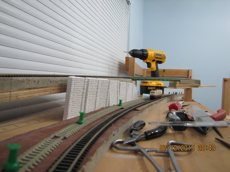
Sunday was to be the start of laying track on the plywood. It had been over a decade(!) since I had laid a turnout, and I had forgotten about all of the prep work required before you could even think about laying one down. Also, while testing running trains, especially the two-axle Schotterwagens, I noticed that I would occasionally see temporary shorts when going through complex point-work. I hadn't fully made my turnouts "DCC Friendly", and I was beginning to see why it was important. for the turnouts already in place, I'm going to have to try some clear nail polish to eliminate those temporary shorts. However, for the turnouts in Staging, I decided to go ahead and make them DCC friendly, according to Allen Gartner's website (Wiring For DCC).
With this in mind, I had to cut both closure rails just before the frog, wire the closure rails to the nearest stock rail, make a hole in the plastic under the frog and solder a feeder wire that will be wired up to a Tortoise switch machine in the future, and cut plastic between first two ties in preparation for feeder wires for power. Rather than doing these one at a time, I used an assembly line to do seven turnouts at once. It would be a good start in getting the tracks laid in Staging. Unfortunately, once I was done with all of that, I looked at the clock and it was nearly 7:00PM. With company coming next weekend, I wanted to put everything away and clean up a bit before calling it a night. So, track laying will have to wait until next weekend - if I have time.
Some things I forgot to take care of included the faulty frog wiring for one turnout on the south end of Murnau Bahnhof and extending the buss wire to the entrance to Staging on the north end. I MIGHT try to get to those this week - again, time permitting. In the meantime, here are some pictures from this weekend.
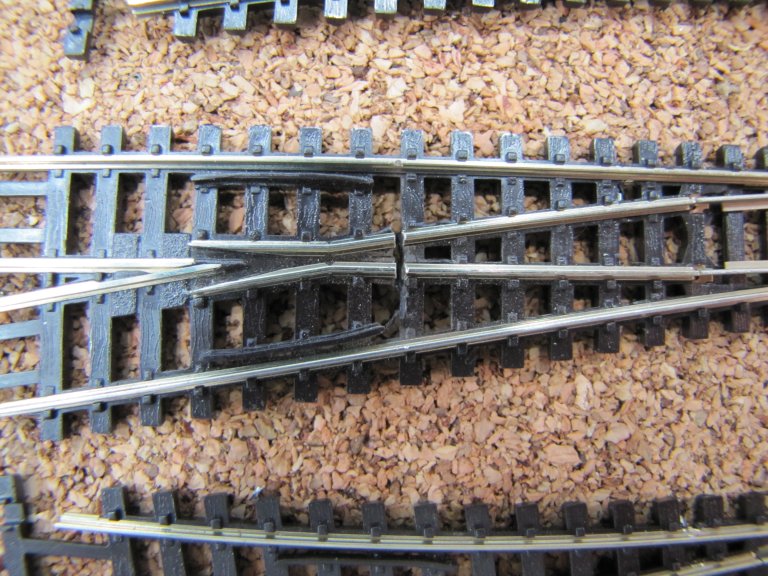 |
| In this photo, you can see the cuts in the rail that I made with a Dremel tool to isolate the frog from the closure rails. This modification should eliminate the temporary shorts that I've been experiencing with my 2-axle Schotterwagens. |
 |
| After making the cuts in the first photo, it's important to wire the closure rails to the nearest stock rail. You can see this in the middle of each turnout shown here. At the very top of the photo, you can see the holes that I made in the plastic at the frog. A wire will be soldered here that will get power based on the position of a Tortoise switch machine - using one of the two internal switches in the Tortoise. |
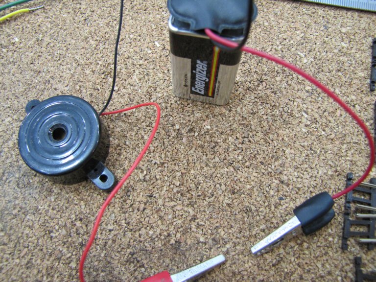 |
| I use this handy-dandy homemade testing tool to ensure the stock and closure rails are properly soldered. The piezo beeps when touching the leads to two rails that are soldered together. I also used it to ensure the cuts I made in the rail were complete. This time, I was looking for the lack of a beep, as I wanted the rails to be isolated. |
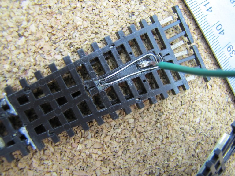 |
| Here, you can see the green wire soldered to the frog. |
 |
| In this photo, you can see what amounts to about 70% of Staging. You can also see the 7 turnouts that I successfully modified to be DCC friendly. The tools are sitting atop 2 of the 4 ceramic tiles I was using to hold down the cork as it dried. I also used them to help with the bow that developed after the cork as glued down. |
July 19, 2015 – Another Control Panel And Working Out The Bugs (23 July 2015)
The previous week did see me make it to the layout room at least once. I polished a good portion of the track in Murnau Bahnhof. I'll probably need to hit a few places again - especially on the south end. Once that is done, I only need to polish the rails on the helix.
This weekend was all over the map again, but this time it was a bit more planned. On Saturday, I worked out a few bugs while running test trains in Murnau. I found that the spur closes to the edge of the layout was completely dead. After drilling a couple of holes and soldering two feeder wires, I went under the layout to wire them up. It was then that I realized that the two original wires for that section of track were properly attached to a barrier strip - but had NO power going to them!! So, I had just wasted time on two unnecessary feeders! Oh well - I hooked them up and ran power wires to both of them on the barrier strip. One issue down.
Next, I found a turnout on the south end that had no power. After fiddling with the green wire to the frog, I realized that it had come lose - likely a poor soldering job on my part. The bad news? This turnout was glued down, and in the middle of a fairly complex section of track. Great. So, I heated up the tops of the frog rails and pushed the wire up against the bottom of the rail from underneath the layout. I tried this for several seconds, let it cool, and then ran a test train over it. It worked - or so I thought. Later in the week, I had the same issue. I check the wire again, and sure enough, it was still loose. I'm going to fix this next weekend. I'll try reheating again. If that doesn't work, I'll drill another hole and add another wire. So, one issue down, one issue deferred until next week.
I didn't find any other electrical issues while running test trains on Saturday, but I did find a bunch of dirty track that had been laying around for over a decade and had never had a powered locomotive roll over it. So, there was a lot of Bright Boy usage. I'll have to polish and paint these tracks next weekend.
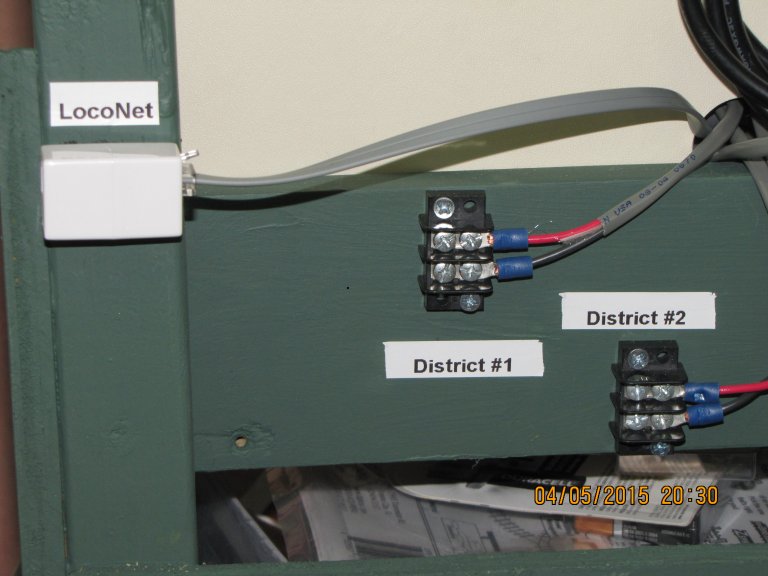
On Sunday I moved a bunch of stuff around so that I could move my Digitrax cart to its final location.. Even though it will continue to move (for now), I wanted to hook up the three districts that I now had on the layout. I ran 14 AWG wire from each district to that barrier strips on the cart and fired things up. Locomotives worked on all three districts! Next, I trimmed some throw wires on the double slip switches and then ran trains that crossed districts - no issues!
I manually switched the tortoises on all of the switches on the south end of Murnau, including the two double slip switches, to ensure every route worked. It turned out that I had one side of a double slip switch and another turnout mis-wired. Once I flipped the black and red wires on pins 6 and 7, everything worked as expected. As I mentioned above, I still need to so some painting, cleaning, and polishing, but I think all of the electrical kinks have been discovered and fixed (except for the one issue with the frog).
Finally, I finished up the weekend by assembling the second control panel for Murnau Bf. I routed out spots for the three hinges, and then attached the hinges as I did for the first panel - attaching the hinges to the panel by sandwiching them between the panel and a 1"x2" board, which spans most of the length of the panel. It's now ready for green paint and then the track diagram for the south end of Murnau.
July 12, 2015 – Busy Weekend + Minimal Motivation = Little Progress (12 July 2015)
Today was the only day I had this week to do anything on the layout. It started out with me getting up late. So, I did a few things on the computer and had lunch. At that point, I realized that the Telekom Cup was on TV (Bayern, Augsburg, Hamburg, and Borussia Möchengladbach). So, I decided to take care of creating a template for the control panel on the south end of Murnau Bf while I watched. Of course, I did NO work while Bayern was playing, and very little work while the other clubs were playing. The good new is, I finished the template. That bad news is, that's ALL I did this weekend!
My goals for this week are to get out to the layout at least a couple of times. Polish some track with a stainless steel washer (BTW, this really does work!), cut the control panel for the south end of Murnau down to size, wire and glue down the two sections of track I recently laid. That way, I'll be set for the weekend.
Oh, one other decision I've finally made is to lay the track on the long piece of plywood I have for staging. I can't really install the 2 DS64s on the south end of Murnau without either laying the track, or reducing the size of the plywood - which I don't want to do. So, I'm going to pull the plywood out, lay the track and drop feeder wires, cut it to size, and then shove it back under the layout. I'm not going to tie it into the track from the helix - at least not permanently. I may clamp it to the helix lead, but I want to be able to shift it around. I've had the sheet of plywood laying in the location of staging for a few weeks, now. With it loose, it hasn't caused me any issues. So, adding the cork and track should be fine as well.
Here are some random shots of the layout, including the fascia/UP5 additions and the new track that I laid.
 |
| In this photo, you can see the pieces of fascia that I added and the UP5. The piece containing the UP5 (just below the DS64s) in the foreground was added, as was the piece to the right of the control panel that goes all the way down past the staging level. Note the piece of plywood under the control panel. This is the piece I'll be using for the staging tracks that I mentioned above. |
 |
| Here is the double-tracked mainline at the top of the Hechendorf Ramp that I had mentioned in a previous blog entry. Each of the two sections consists of two pieces of Peco Code 55 track - one with concrete ties and one with wood ties. The white retaining wall needs to be cut and filed - this was just a test fit to see what it would look like. |
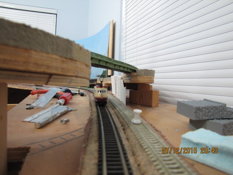 |
| A view that will be impossible once this area is completed. This is the other side of the bridge that is used by the branchline to Oberammergau. This area will be behind the backdrop for the branchline, and there will be landforms added here as well. It'll be impossible to get a camera in here, at that point. |
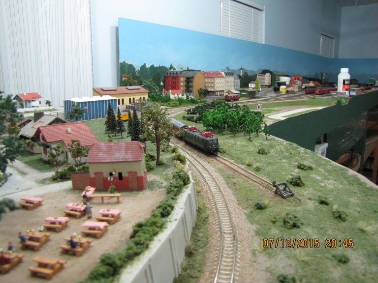 |
| An overall view of the "finished" section of the layout, which is the north end of Murnau. I still need to add signals and catenary, however. |
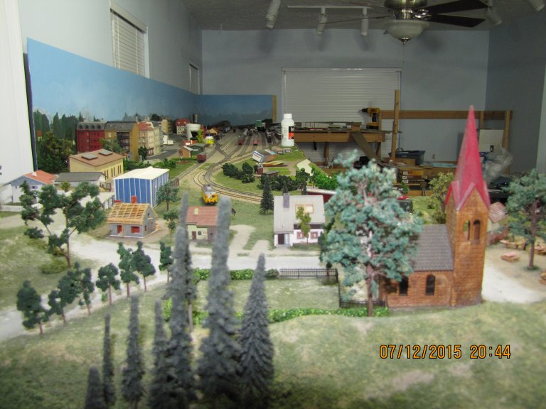 |
| A full-length view of Murnau. In the very back (to the left of the yellow drill) is the branchline bridge and the retaining wall that are in the photos above. |
July 6, 2015 – Laying Track For The First Time All Over Again (9 July 2015)
The last day of my four-day weekend was not as productive as I had hoped it would be. However, I did get some things done. I laid some cork roadbed down on the double track mainline that heads south out of Murnau Bf. I had to modify a jig I made long ago for sanding off the excess cork because the pieces I was working with were very wavy, and I couldn't get them to calm down enough to get a good sanding done. So, I added a guide out of 1/8" plywood that covers about 1/3 of the cork in order to hold it down as I sanded. It worked!
Once I laid the cork, I took a shot at laying track for the first time in about 10 years. Of course, it couldn't be straight, and it couldn't be a single track. Nope, it was the curved double mainline on an incline at the top of the Hechendorf Ramp as it goes under the bridge for the track to Oberammergau! So, I started by cutting away ties, shaping the track with the larger radius, and then soldering two pieces of track together. Not too bad. Trying to get the track attached to the double slip switch using plastic, insulating rail joiners was a different matter. I had forgotten what a pain these can be. I think I ruined two of them.
I did the same thing for the track with the smaller radius, and that went a bit smoother. I was starting to get the hang of it again! I drilled holes between two ties on each rail segment, in preparation for wiring, but decided to stop there. This now gives me track located in three districts in very close proximity. So, one of my goals for next weekend will be to wheel the cart with all of my Digitrax equipment over to this area and hook up the 3 districts to see how the PM42 handles them. Ultimately, this will be the final location for this cart. However, until this section (upper and lower decks) is completed, the cart will continue to move around.
I finished up the day by cutting away some of the subroadbed around Murnau Ort. I need to be able to add a retaining wall that won't get in the way of the track. Once the modifications were complete, I test fit the retaining wall. It turned out that I had to sand down the first segment of the wall that was closest to the bridge. I may try to install the wall next weekend. We'll see...
Speaking of next weekend, I'll be a bit busier than expected on Saturday. So, my time on the layout will likely be zilch. I may do some wiring on Sunday, and possibly start working on the diagram for the control panel for the south end of Murnau Bf. It's tedious work, and I don't want to get going on another big project until I force myself to finish the control panel.
July 3, 4, 5, 2015 – Four-Day Weekend! Lots of Things Crossed Off My Checklist (5 July 2015)
The Independence Day holiday weekend has allowed me to get several little items done - and I still have another day to go! I can finally say that I have now installed all Tortoises in Murnau Bahnhof! I installed the last two Tortoises, which were for the second double-slip switch on the south end of Murnau. I wired up the frogs to track power on these and a couple of other turnouts. I also started my second district, which is the line to Oberammergau (KBS 963). I only had a turnout, a Tortoise, and a piece of track that needed to be hooked up, but it was a start.
I had to do some cleaning up and rearranging. Since I'm done (until I get some signals shipped to me - likely sometime in August) on the north end of Murnau, I needed to shift a bunch of stuff under that end so that I could get to the south end. I'll be starting on the control panel on that end in the next week or so.
I added some additional pieces of the fascia - filler pieces around the control panel and the DS64s. I also mounted a UP5 to the fascia just below the DS64s. This allows me to plug in my throttles. I had been using the UP5, but it was laying on the layout - attached to nothing.
I also knocked off one of my "miscellaneous" tasks last night. I was pretty much done for the night, so I took a quick look at my checklist. I marked a couple of items off that I had taken care of in the last day or two. Then, I noticed the "Try using ELO to remove the BASF and RAG lettering" on some of the ballast hoppers (Schotterwagen) that I had purchased. So, I drug out the ELO (Easy Lift Off), grabbed a toothpick, and gave it a shot. As I dabbed the ELO onto the first BASF logo, it appeared to be taking effect immediately. So, I started to scratch at the logo with the toothpick. What appeared to be a logo slowly disappearing was actually brown paint coming off and spreading around on the logo - the car was actually a very light gray (almost white), and was painted brownish red (not really boxcar red). I just figured the car was molded using plastic that was the brownish red color - WRONG! It almost appears as if the logo and all markings on the care were created by applying tape or something prior to painting the car. Once dry, the tape would be removed to reveal the logo and markings. I could be wrong, but they were the exact color of the plastic underneath - I never saw a decal or white paint lift up off of the car. So, now I had to figure out how to color match the rest of the car... great...
I figured Polly Scale boxcar red would be the most obvious choice. As mentioned above - wrong. It was too gray, too light on the brown, and had very little red. That's when I called in my wife, who's an artist. I don't have a lot of Polly Scale colors - I never have to mix these to get a particular color, so I just have the colors I know that I need. So, we had to move to craft paints. I knew I'd need a brown and red mix, but was uncertain where to start. My wife eyeballed one of the cars in good light, and immediately picked out a Ceramcoat Dark Brown and an Americana Cherry Red. I started playing around a bit by adding red to the brown. At about 60% brown and 40% red, the color was an exact match! Unfortunately, I say "about", because I wasn't very scientific about it. I finished 5 cars, but then found another one I wanted to do. My paint was drying, so I had to mix some more paint for the last car. That one isn't an exact match, but it would be tough to spot by someone who didn't know. All in all, I'd call that a very successfully completed task! I have six cars completed, and I know the two colors (and the approximate ratio) I need in order to do more.
I may post a picture of the new fascia additions, including the UP5, in the near future. Most of the stuff I've been doing isn't really "photo worthy". However, I've decided to "head south" on the layout instead of working on Staging below Murnau. This means I'll work on Murnau Ort soon, which would be a good photo-op. For now, I'll be working on the second control panel for Murnau Bahnhof's south end. I should be able to start working on that tomorrow.
June 27, 2015 – Turnouts On North End of Murnau Bf All Wired Up - Photos To Prove It! (28 June 2015)
After a couple of weekends off due to a trip to Iowa to visit my mother, I was able to work on the layout for most of the day on Saturday. More importantly, I was able to get all turnouts on the north end of Murnau Bahnhof wired up!! Eight of the turnouts are wired to the two DS64s. The remaining four are wired to DPDT switches for manual use by switch crews.
Before I left for Iowa, I had spent a little time on the layout, setting up routes via the DS64s. I ran into a snag when I got to a route that had 6 entries (meaning, six turnouts are fired at once to produce the desired route). No matter what I did, I couldn't get turnout #6 to work in the route. It worked just fine when bringing it up on my throttle by itself and either throwing or closing it. Hmmmm... It was only after I had made the trip to Iowa that I suddenly realized that turnout #6 was on the second DS64 - and, I hadn't programmed the second DS64! Being without any cell phone or Internet connectivity has a tendency to clear your head, I guess!
So, yesterday, that was the first thing I did. Once DS64 #2 was properly programmed to accept route commands from a local push button, things worked as expected.
Once I had confirmed that, it was time to finish installing the remaining 4 push buttons and 3 DPDT switches. I originally thought I only had 2 DPDTs to install, but I had apparently overheated on of them a couple of weeks ago. Its performance was erratic, and then it stopped working completely.
After all of the push buttons were installed and wired up to the DS64s, I finished up programming the remaining routes. It was very cool to finally hear up to SIX Tortoise switch machines being activated all at once!
I ran a locomotive with a small freight train through all of the routes. All turnouts were properly aligned, so no further adjustments were required. I did notice that some of the backs of the wheelsets on the freight cars were brushing up against closure rails on some of the turnouts - especially when performing a backing move. This causes a momentary short. Now I'm starting to understand the reasoning behind the suggested modifications to make Peco turnouts "DCC Friendly". Those modifications would've eliminated this issue. I plan on trying another workaround that I had seen on one of the Yahoo forums, which is to dab a little clear nail polish on the backside of the closure rails. I'll try that next weekend. Hopefully, that will take care of this minor, but irritating issue.
Next weekend is Independence Day, which means a long weekend. I've extended it by another day by taking Monday off. I have some 22 AWG wire on order. I'm not sure it will get here by next weekend. However, I have several other things I can (need to) do - like wiring up those last two Tortoises on the south end of Murnau. I also need to add the south end portion of the control panel and also add a little more fascia. I also have a couple of side projects I'd like to start. So, I should have plenty to do next weekend.
As promised, here are a couple of photos of the finished control panel for the north end of Murnau Bahnhof:
 |
| The completed control panel for the north end of Murnau Bahnhof, along with the two DS64s. |
 |
| Another angle with just the control panel. The red push buttons are for routes. The four DPDT switches (3 along the bottom, 1 near the top) are for manual control of individual turnouts by crews who are performing switching moves with freight cars. The routes can be invoked via the push buttons, a Digitrax throttle, or a computer program, such as one from JMRI. The turnouts with the DPDT toggle switches can only be used locally at the control panel. |
June 6, 7, 2015 – Red LEDs, Toggle Switches, And Even MORE Wire! (7 June 2015)
So, I worked as many hours as I did the previous weekend. However, I didn't feel like I got as much accomplished. I can tell you that wiring up the DS64s is a breeze compared to the DPDT toggle switches I tried this weekend.
I started out by wiring up the last Tortoise to the DS64. Next, I turned my attention to retro-fitting some red LEDs in place of some of the green LEDs. I wanted an indication for any switch that came off the main line. If one of these switches was thrown, I wanted a visual indication, so that people had a better chance of remembering to line it back to the main line when done with their switching duties. So, if an operator sees any red LED lit up when coming through Murnau, they know someone didn't do their job, and realign the turnouts once they were done switching!
Once this was done, I decided to start working on the 4 turnouts that would use toggle switches for control. The first one went slow, but it worked just fine - LEDs and all. The second one took up most of my Sunday afternoon. To make sure I had the LED wired properly and the toggle switches in the right orientation, I did a lot of rigs - loose wires twisted together before doing any soldering or adding spade connectors.
During the toggle switch orientation testing, I noticed that this turnout would switch nicely in one direction, but it wouldn't move at all in the other direction. I had to take the Tortoise down and inspect it. I opened it up and noticed that one of the gears was reversed! I open up all of my Tortoises, and make a couple of cuts on the contacts to better ensure that I don't get momentary shorts while the Tortoises are activated. Well, on this one, I had messed up in reassembling. Yet another reason to test, test, test, before I start building my staging yards. It will be nearly impossible to do what I just did once staging is complete.
Once I took care of this Tortoise and slapped it back on the layout, I started wiring this one up. Upon completion, I noted that it worked fine in one direction, but not the other. At first, I thought it was the same issue. However, I hooked up another Tortoise, and it had the same issue. I checked the LEDs, and they seem fine. I'm thinking a trashed the toggle switch. I have one more test I can do, but that will have to wait until next weekend. I have this one, plus two more turnouts, and I'll be done with the north side of Murnau Bahnhof. It'll then be time to move to the south end, where I still have two Tortoises to add to my last double slip switch.
I'll try to add some photos once I'm done with the north end control panel. I'm not sure I'll post a "behind the scenes" photo, however. I'm not very good at keeping my wiring neat. That is a separate planning stage all in itself! And, by the time I get started, I get so pumped that I'm actually making progress, that I pretty much ignore this step.
May 30, 31, 2015 – DS64s, Green LEDs, And A TON Of Wire! (7 June 2015)
Well, I took the plunge and drew the track diagram of the northern half of Murnau Bf onto the control panel - with the help of my wife. We used carbon paper to trace the diagram onto the control panel. We taped the carbon paper onto the panel, then then taped the diagram on top of the carbon paper. Using a ruler, to ensure straight lines, we then went over the lines with a pencil. Once the carbon paper was removed, we used a white paint pen and a ruler to go over the lines that had been left by our tracing. I have to say, it looks pretty good. A little touch-up here and there, but that was it. I was going to seal it with a gloss coat, but my wife got me gloss medium instead of gloss coat. I tried it anyway. Big mistake. The gloss medium has body, and left fairly deep brush marks. I'm hoping a few coats of gloss coat will eliminate, or at least reduce these brush marks. We'll see...
Once the control panel was drawn, it was time to drill some holes. Talk about taking the plunge! I really didn't want to screw this up, so I simply started with LED placement. I went over the whole plan several times in my head before using an awl to mark the hole locations. Then, I went over it a few more times before actually drilling. Masonite isn't really suited to drilling holes. Little mounds are built up around the drill bit. I cleaned these up with a couple of different Exacto blades on the front - being very careful to not take any paint off. The back got a combination of Exacto blades and sandpaper.
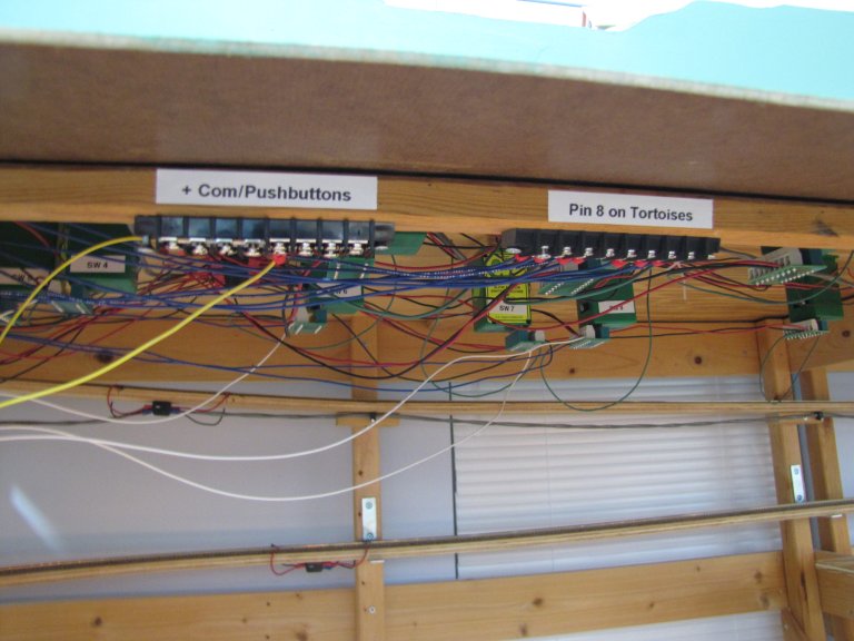
Once the holes were made I began the whole process of wiring up the DS64s, the LEDs, and the 8 Tortoise switch machines that would be included on the DS64s. The other 4 Tortoises will be manually thrown with toggle switches. These turnouts lead to spurs and are primarily used for shunting . The train crews would switch these manually. I managed to wire up 7 of the 8 Tortoises before I called it a weekend.
Part of this whole process is to test track and turnouts as I go. This is actually the fun part, as I get to run a train or two over the newly wired turnouts. I need to make sure things are solid before I start working on staging. It's a good thing I did this as I found that one of the turnouts didn't completely throw the closure rail, so that it was snuggly up against the stock rail. Luckily, this was a minor adjustment, as this area of the layout was already ballasted! (Part of my time when funds were non-existent, but I had plenty of scenery material.) I just unscrewed all but 1 screw holding the Tortoise to the underside of the layout and rotated is slightly. It now works fine! Whew!
May 26, 2015 – I Must Have An Internal Flywheel - Excess Momentum From The Weekend (26 May 2015)
Just a quick note. I carried my momentum into the work week! I finished up wiring as much as I could before I begin work on the control panel, itself. My next task will be to create the layout diagram of the north end of Murnau Bf onto the existing control panel. Once that's done, it's time to drill holes, add components, and finish up the wiring. This may have to wait until next weekend. We'll see...
May 23, 24, 25, 2015 – Serious Progress Over Memorial Day Weekend! (26 May 2015)
It's amazing what you can accomplish when you have some free time and are focused on the task at hand! This weekend, I was super motivated to get some work done. I'd say it was the most I've accomplished on the layout in a 3-day period in years!
I started out by checking the fit of the 20"x 96" piece of plywood that would be the basis for my lower level. I wanted this to be are large as possible, so that I can add the staging tracks to the plywood before I install it under Murnau. I don't want to be leaning in between the levels, trying to drill holes for feeder wires or trying to get those little rail joiners onto the track - especially with a bunch of turnouts using those plastic insulating joiners! It turned out that the 8-foot length was 6" too long, so I whacked off 6" from the end. 90" is a good length to work with, so I was extremely happy. I think the whole yard will be about 10 feet in length, so I'll have another board that is around 2.5 feet long. This is good, considering my yard ladders are about 2 feet in length. So, I can put on of the ladders on this board.
Next, I installed a piece of plywood that spanned the two levels on the very northern end of Murnau Bf. This is where I would mount the 2 DS64s for controlling the northern end's turnouts. I wanted these modules set back a bit, so that they weren't in the aisle. I was going to put them under the layout, but you need access to them for programming, and also to see the light indicators.
I'm not using DS64s for all of the turnouts. My general plan is, if it's a turnout associated with the mainline, or the movement of passenger trains, I wanted it hooked up to a DS64. This would allow for routes - both with push buttons on the control panel, the Digitrax throttles, and, eventually, via a computer program used by a dispatcher. All other turnouts would use toggle switches at the control panel. My thinking is that these turnouts would typically be for switching moves. Those would likely be hand thrown by the train crew doing the switching. Plus -- It saves my a LOT of money by not purchasing so many DS64s! Right now, I thinking KBS963 to Oberammergau won't use any DS64s. There are agents at each station that handle the switching and even actuating crossing arms near the station at level crossing with roads! That was the case in the time period I'm modeling, anyway.
After the plywood for the DS64s were completed, I started working on extending the fascia for the upper level. I cut an 8-foot piece of masonite that would cover the side of the base for Murnau - the 1"x4" frame, plus any plywood, homasote, and scenic materials. Below this, I would hang my control panels from hinges. I came up with this idea while staring at the layout and drinking my morning coffee on Saturday. I wanted access to staging without the hinges, but I also wanted to be able to access the underside of the top level - I'm sure I'll need to get in there for maintenance at some point. Hinges would also allow me to access the elongated helix, located at the back.
So, I cut another 8-foot length of masonite for the control panels. To provide access to staging, I decided that my control panels would have to be 6" tall. It's not a lot of space for LEDs, pushbuttons, and toggle switches, but I think it will be sufficient. I plan on having two of these panels - one of the south end of Murnau, and one on the north end of Murnau. I routed out a space for the hinges as well. For now, I only did the northern end - I wanted to make sure it worked before I screwed up two of them!
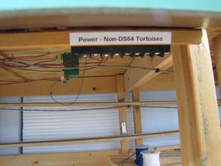
Installation went smoothly. Once this was done, I painted everything green to match the rest of the fascia. After the paint dried, I mounted the two DS64s and began doing a little wiring. I hooked up one wire for power from the DS64s to the Tortoise machines. I hooked up the other power wire to a barrier strip, as these will be wired to LEDs. So, they can't go straight to the DS64s. I also wire the "+ COM" wire to a barrier strip, which will be used with the pushbuttons.
Here are some photos of my progress:
 |
|
| Here, you see the top part of the fascia, extended 8 feet. Below that, you see the two DS64s. Next to the DS64s is the control panel on hinges. | |
 |
|
| This is what the control panel looks like fully in the "up" position. | |
 |
|
| A close-up of the underside of the control panel. It will soon be littered with the backs of LEDs, pushbuttons, and toggle switches. In order to limit my chances of screwing up, I've attempted to add labels to everything. As you can see in the background, I've even labeled the Tortoise switch machines ("SW 1", "SW 2", etc.). | |
 |
|
| This is where the power will come from for the Tortoises not attached to DS64s. I'll still be using LEDs for these turnouts, but they'll use toggle switches instead of being part of a route and utilizing pushbuttons. | |
May 22, 2015 – Out With The Old, In With The New! (22 May 2015)
Since I'm on a roll, here's a quick update from today. I replaced all of my existing edge card connectors on the south side of Murnau Bf with the new SNAPs from ACCU-LITE. It made me realize just how many of these things I'll need. I ordered 24, initially, and that won't even cover Murnau Bf! It looks like I'll be ordering at least a couple more 12-paks.
I also went to my local DIY for some plywood and masonite. It's been about 10 years since I purchased any wood. All I have to say is, "Wow!". The quality of wood products at the big DIY stores just completely sucks! Also, apparently we no longer have 1/2" plywood. It's now 15/32"!? I can see that if I want even minimal quality wood, I'm going to have to find a lumber yard. I know of at least one that isn't just for contractors. I'll head down there next time.
Anyway, the reason for the plywood purchase was to figure out how I would be doing my lower level staging yard. The masonite is for control panels for the turnouts and DS64s. However, I don't want to attach these to the front of the top level if it will interfere with building the lower level later on. So, I'm experimenting with the wood to figure how best to build the lower level. I'd love to get the track down on the wood before I install it under the top level. That may not be something I can do completely. However if I can at least get the switches installed, I'd feel much better about it. Regardless, my main concern at the moment is if I can build the control panels this weekend.
May 17, 2015 – Experimenting With A DS64 - Just Call Me The Nutty Professor! (22 May 2015)
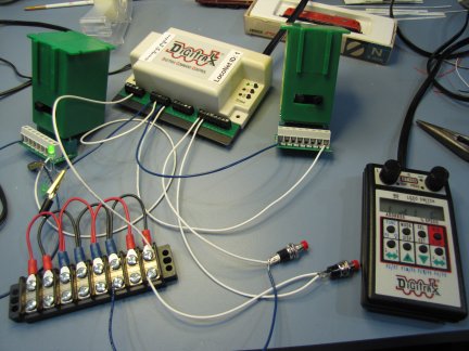
I recently received two shipments of electrical items, so that I could start wiring up the Digitrax DS64s to handle my turnouts in Murnau. I did some experiments using pushbuttons and a Digitrax throttle to control two turnouts. I first did individual turnouts, and then I tried using routes. After getting the wiring correct, the actual programming of the DS64 was pretty straightforward. I will say that in order to get routes to work with pushbuttons, I had to refer to a knowledge base (KB) article on the Digitrax site. There was an additional OptionSwitch (OPSw 15) that needed to be set to the "closed" position. In the original documentation that came with the DS64, it makes not mention of this setting. Yet, without it, routes don't work with pushbuttons!
LESSON: Always check the Digitrax KB articles if you have issues or questions with something you're trying to accomplish with one of your Digitrax components!
 |
 |
|
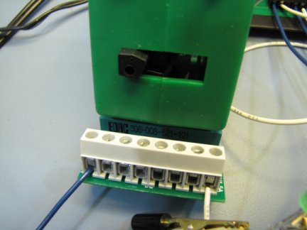
| Here is my test setup for the DS64. I had already tested with the throttle, and was now working with the pushbuttons. I hooked up to LEDs for the first Tortoise, to test reversing 2 LEDs in parallel with one of the power feeds for the Tortoise from the DS64. | Here is a close up of the SNAP by ACCU-LITES. There is an edge card connector on one end, which slides onto the Tortoise. The other end is a bank of 8 screw terminals. Having this flexibility is extremely important, in my opinion, when dealing with a multi-decked layout, where space is a premium. This avoids having to get into some advanced yoga position to solder a wire to a Tortoise. Simply pop the SNAP off and deal with the screw terminals in a comfortable position! |
As mentioned in the second caption above, I'm using SNAPs by ACCU-LITES for all of my Tortoise installations. They're about $7 apiece, so they're pricey. However, as I get older, convenience becomes more important. I had some nice edge card connectors that I was using previously. After the initial order ran out, I couldn't find these exact items anymore! The company that I purchased them from went out of business. Also, I've had a couple of these where I had the spade pull out when I would disconnect wires. So, I've decided to replace all of these as well. Again - I don't want to be under the top level any more than I have to!
May 3, 2015 – At Last! My Enclosure Is Complete! (22 May 2015)
I've actually had some time in the last month or so to work on a few things. I had an enclosure from a previous job that was a prototype, and was being thrown away. I thought it would make a great enclosure for some of my Digitrax equipment, so I grabbed it from the scrap heap. It had a 3.0 amp power supply that I upgraded to a 3.5 amp power supply - another victim rescued from the scrap heap. This enclosure has a temperature sensor, which starts a fan if it gets too hot inside. It even has a heater, in case it gets too cold! It was designed for indoor/outdoor use. I'm guessing the heater will never be used.
I built a rolling rack on which to mount the enclosure - I need it to be mobile during construction. Everything can be disconnected from the back. LocoNet, all four track districts attached to the PM42, and the program track. All power comes from a power strip mounted on the back.
The added benefit is that I was able to add a shelf that I use to store some other Digitrax components. I think it turned out nicely!
 |
| This is the back view of my enclosure and rack. Completely self-contained! I could take this to anyone's layout and hook it up. |
 |
| The front view of the enclosure and rack. The door on the enclosure is closed. Look at all of the room I have for my Digitrax purchases on the shelf! |
 |
| Enclosure door open. The command station, a DCS100, plus the PM42 power management board. |
 |
| A close-up of the interior. Note the wider board that is attached to the PM42. This is an ACCU-LITES product that makes hooking up the PM42 much simpler and straightforward. No tedious soldering (and I don't mind soldering!), and it's more sturdy. I'm very happy with the PM42 Breakout Board and the SNAPs that I purchased from ACCU-LITES! |
 |
| This close-up view of the back shows the labels I created, so that I don't get confused when I have to hook everything up. |